Voltage Drop in Cables: When 2.5 mm² Is Too Little
Voltage drop explained for UK homes: the mV/A/m method, BS 7671 limits (3% lighting, 5% other), worked examples and how to fix a long run by upsizing the cable.
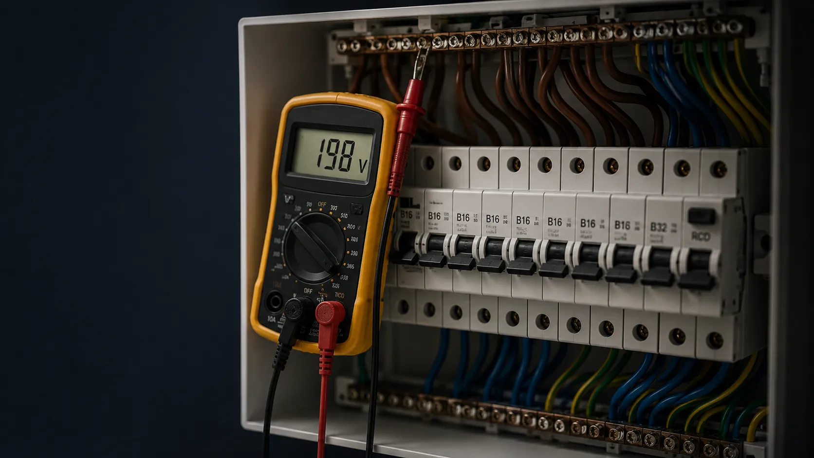
A washing machine in a garden outbuilding kept dropping out of its heat cycle, every other wash. The owner spent half a year swapping heating elements, ringing the service line, falling out with the shop he'd bought it from. Pointless. The machine was fine — the fault was voltage drop in the cable. When I turned up with a multimeter and measured right on the terminals while the heater was on, I got 198 V. Back at the board, a healthy 228. Between the two sat 30 metres of 2.5 mm² twin-and-earth, with a borehole pump drawing at the same time. The run swallowed thirty-odd volts, the machine's controller saw the supply sag and locked the heat out. That was the whole "fault."
I keep that job in mind every time someone says "but the breaker holds, so what else could it be?" Plenty could. The breaker holds because a breaker counts amps, not volts. Your washing machine, shower or welder don't care about amps in the slightest — all they care about is what arrives at the terminal. And when you run a thin conductor a long way, what arrives at the terminal is nothing like what left the board.
Here's everything worth knowing: what voltage drop is and why it's invisible, the mV/A/m method the UK uses (plus the formula behind it), the BS 7671 limits, three worked examples that cover most real situations, a cheat-sheet of maximum run lengths, and three ways to fix it once the numbers come out ugly.
What voltage drop is and why you can't see it
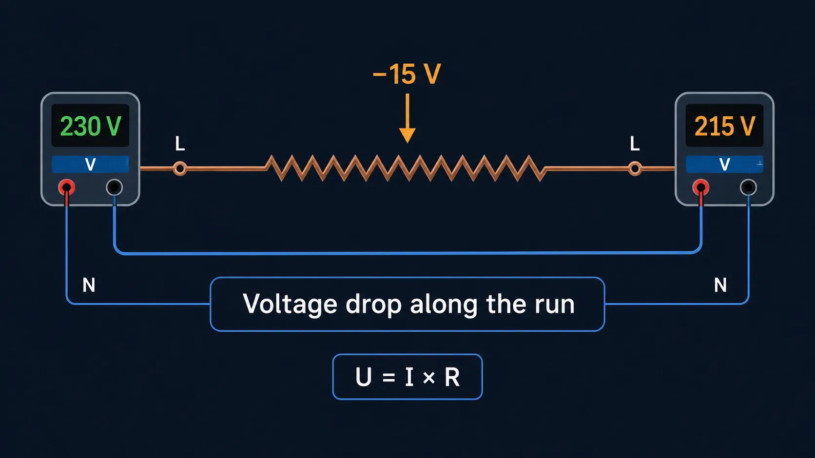
A cable is a resistor. A long, bendy resistor, but a resistor all the same. The thicker and shorter it is, the less it fights the current. Ohm's law sets it out — U = I × R: at a given current, more resistance means more volts "dissolving" inside the conductor itself instead of reaching the appliance. That's the whole of the physics. The only question is the numbers — how much dissolves, and whether the kit at the far end notices.
Why a 32 A breaker holds and there's still a problem
A breaker is an electromagnet and a bit of bimetal. It lets go when the current climbs past its rating — say 32 A on a ring, or 20 A on a radial. That's it. There's no voltage sensor anywhere inside it. So the situation "the far socket has sagged to 205 V while it's drawing 13 A" simply doesn't exist as far as the breaker is concerned: 13 amps is under the rating, so all's well, no reason to trip.
Look at it in numbers. Take 2.5 mm² copper, a 30 m radial, a 16 A load, 230 V. Drop the figures into the formula (more on it shortly): ΔU = 2 × 16 × 30 × 0.0175 / 2.5 ≈ 6.7 V. That's under 3% — fine on paper. And the breaker won't so much as twitch through any of it; you could lose ten volts or twenty and it'd sit there like a stone, because the current never leaves the band it watches. The breaker calculator will match the right rating to your cable, but it won't tell you the volts at the end of the run — that's a separate job.
One detail worth a line. UK supplies are nominally 230 V single-phase — harmonised with the EU years back — although your socket still reads somewhere in the 230–240 V region in practice. Every figure in this article is worked from 230 V, which is the conservative choice and leaves you a little more headroom.
So the takeaway is plain. The breaker and the voltage drop live in parallel universes. The first keeps the copper from cooking. The second nobody catches but you and a calculator. Want to know what's really at the terminal? Either work it out with the formula, or measure it with a multimeter under load. There's no third way.
How voltage drop breaks appliances — real cases
Now the part that actually hurts. Voltage drop isn't an abstract number in a calculator. It's specific faults on the washing machine, the shower, the welder. Here's the list of symptoms I use to spot the problem before I've even reached the job.
A washing machine landed on a customer's bench. "The Bosch keeps cutting the heat, two engineers have already swapped the element and it's no better." Brought my own tester. Measured the voltage at the element terminals with the heater on — 198 V. At the board, 228. The cable was about 25 metres of 1.5 mm² (on a washing machine!) buried in screed. The machine was perfectly healthy; the controller just saw the supply too low and locked out the heat, because heating on a sagging supply can damage it. Pulled a dedicated 2.5 mm² run instead, and the Bosch stopped sulking.
LED lights are their own story. A bloke bought a batch of cheap fittings for his workshop and hung them off 1.5 mm² on a forty-metre run. Rings up: "they're flickering." Textbook. Measured 205 V at the fitting with three lamps on. A cheap LED driver can't hold its output steady on a wobbly supply, so it starts hunting the brightness up and down. There's your "flicker," and the headache that comes with it half an hour later. Decent drivers — Philips, Osram and the like — sail through 180–260 V, but even they can start to misbehave once the supply sags below about 207 V.
Showers are the classic at home. You hear the lights dim every time someone hits the electric shower upstairs — that little dip as the heater kicks in. On a long, thin run that dip turns into a real problem: a 9.5 kW shower can pull 40-odd amps, and if the cable's underrated for the distance, the terminal voltage falls far enough that the unit runs lukewarm or throws an over-temperature cut-out. People blame the shower. Nine times out of ten it's the cable.
A fridge or freezer is the sneakiest of the lot. The compressor's starting surge is five to seven times its running current. An appliance that draws 1.5 A in normal use can grab 8–10 A for the first hundred milliseconds at start-up. On a thin, long run that's a momentary 25 V dip right at that instant. Everything else on the circuit sees the lurch: the PC reboots, the router drops Wi-Fi, the microwave clock blinks. "My supply keeps glitching" — the classic complaint — is often the household's own fridge, talking through a thin conductor.
The inverter welder is my favourite. A chap was running one in his garage — 2.5 mm², 35 metres. Strikes the arc, the surge jumps to 30–40 A, the voltage at the electrode dives to 175 V. The weld comes out like a dog's dinner. He blamed the machine. It was the cable: for a 32 A peak over 35 m he wanted 6 mm², not 2.5.
Bottom line — the breaker sees none of this. The appliance sees all of it, and tells you, through error codes or a ruined weld. Before you run a conductor 30 metres and beyond, work out the loss. Or just step up a size, even if the smaller one passes on current. The extra costs pennies; the problems cost a fortune.
The formula — three minutes with a pencil
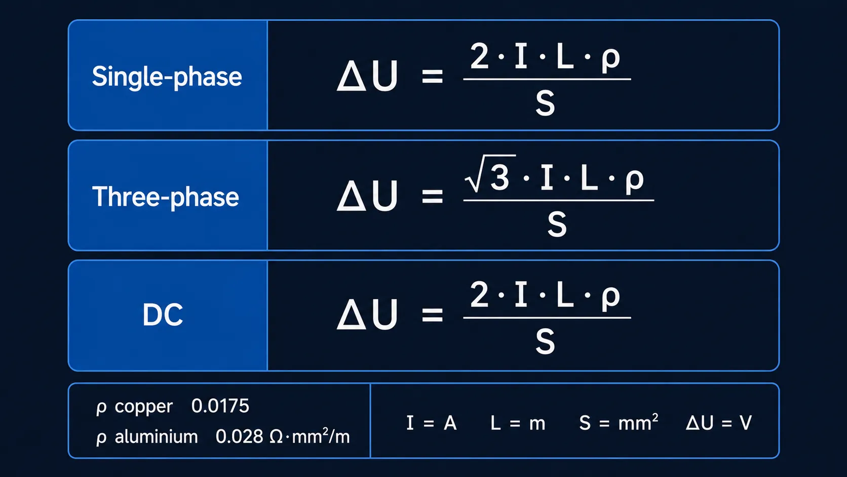
A calculator's handy, but the formula takes thirty seconds and you can actually see WHY the conductor sags, instead of pulling a number out of thin air. There are three flavours — single-phase, three-phase, DC. Same logic, different constant. Don't fancy the maths? Here's the voltage drop calculator. But read on — you'll understand why 2.5 mm² over 30 m is borderline for a kettle and a disaster for a shower.
Single-phase — the main formula
Here it is: ΔU = (2 × I × L × ρ) / S
Reading it off:
- ΔU — voltage drop, in volts
- I — load current, in amps
- L — one-way run length, in metres (NOT there-and-back!)
- ρ — resistivity of the metal: copper 0.0175 / aluminium 0.028 Ω·mm²/m
- S — conductor cross-section, in mm²
A worked one. At my place there's 30 metres from the board to the kitchen, 6242Y 2.5 mm² twin-and-earth, a 2 kW kettle on the end. Current: 2000 / 230 = 8.7 A. Plug it in: 2 × 8.7 × 30 × 0.0175 / 2.5 = 3.65 V. As a percentage: 3.65 / 230 = 1.6%. Fine — the kettle boils as it should and nobody's the wiser.
Now swap the kettle for a 3.5 kW immersion. Current 3500 / 230 = 15.2 A, plug it in: 2 × 15.2 × 30 × 0.0175 / 2.5 = 6.4 V = 2.8%. At the element terminals you've now got 223.6 V instead of 230. Not a catastrophe, but switch something else hefty on alongside it and you're over the 5% line. And the immersion's real output falls with the square of the voltage. Learn the formula — it's thirty seconds that saves you half a year of grief.
The mV/A/m method — how the UK actually does it
Out on a real job, electricians here rarely reach for resistivity at all. Instead they use the mV/A/m value straight out of BS 7671 Appendix 4 — the millivolts dropped per amp, per metre, for each cable size. For 2.5 mm² twin-and-earth that figure is 18 mV/A/m; for 1.5 mm² it's 29; for 4 mm², 11; for 6 mm², 7.3; for 10 mm², 4.4. The sum is then dead simple:
ΔU = (mV/A/m × I × L) / 1000
Take that same 30 m run at 16 A on 2.5 mm²: ΔU = (18 × 16 × 30) / 1000 = 8.6 V. Notice the mV/A/m number already bakes in the there-and-back of a single-phase pair AND the conductor's real resistance at working temperature — which is why it lands a touch higher than the bare-resistivity sum above. That's the figure to trust for a UK job. Both methods describe the same physics; the tabulated one is simply pre-chewed for you. (For three-phase, the table gives a separate, lower mV/A/m value per cable size — use that one, don't improvise.)
Three-phase — where the √3 comes from
For three-phase the formula reads ΔU = (√3 × I × L × ρ) / S, where √3 ≈ 1.732. Same logic, different constant.
Why not 2 like single-phase? Because in a balanced three-phase load the current returns not through a neutral but through the other phases, each shifted by 120°. Roughly: single-phase has a path out and a path back (hence the 2). Three-phase smears the return path across the neighbouring phases, with partial cancellation. The maths of the sine waves lands you on exactly √3.
A worked example: a three-phase immersion bank, 12 kW, 4 kW per phase. Current per phase 4000 / 230 = 17.4 A. Run 25 m, 4 mm² cable. Drop: 1.732 × 17.4 × 25 × 0.0175 / 4 = 3.3 V. Against the 400 V line voltage that's 0.8%. That's why three-phase always wins for heavy loads — for the same total power the per-phase current is a third of single-phase, and the constant's lower too. Most UK homes are single-phase, mind; three-phase tends to turn up only on larger properties, workshops or with a big EV/heat-pump setup. If you do have it, check the load is spread evenly across the phases with the phase balance tool — a lopsided load hands all that advantage straight back.
DC — for inverters and 12 V
Same formula as single-phase: ΔU = (2 × I × L × ρ) / S. The 2 is there too — plus and minus, two conductors, the resistance doubles.
The catch lies elsewhere: in DC the voltage is low. A 12 V inverter, 1 kW load. Current: 1000 / 12 = 83 A. Not a typo — eighty-three. Cable 6 mm² over 5 metres. Drop: 2 × 83 × 5 × 0.0175 / 6 = 2.4 V. Sounds like nothing, but it's 20% of 12 V — the inverter beeps and shuts down. So the rule for low-voltage DC (12–48 V): the conductor wants to be two or three times fatter than the comparable 230 V AC cable — not because "DC vs AC" (the cable's resistance is identical) but because at the same power the current is ten to twenty times higher. The Chinese diagrams that come with this kit often quote cross-sections in AWG — convert to mm² with the AWG converter.
The bits worth understanding — resistivity and constants
Two things people muddle. First, why copper and aluminium behave so differently. Second, where the 2 and the √3 come from. Quickly.
Resistivity — copper vs aluminium
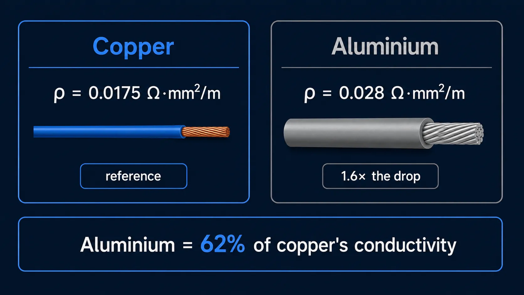
The figures are simple:
- Copper: ρ = 0.0175 Ω·mm²/m
- Aluminium: ρ = 0.028 Ω·mm²/m
Aluminium has 1.6 times the resistivity of copper — about 62% of the conductivity (so roughly 37% worse). In practice: an aluminium cable of the same size gives 1.6 times the voltage drop of copper. Put another way — to match copper's drop, aluminium needs to be one and a half sizes thicker. For UK domestic work this is mostly academic — homes are wired in copper twin-and-earth, and you'll only meet aluminium on older sub-mains or a long supply tail to an outbuilding. But the maths still bites where it appears.
A real case: a friend ran 4 mm² aluminium 40 m to a sauna heater. The 3 kW element drew 13.6 A. Drop: 2 × 13.6 × 40 × 0.028 / 4 = 7.6 V (3.5%). The heater took 15 minutes to reach temperature instead of 10. And that was with new cable — after a decade, aluminium oxidises under the terminal screw and the resistance climbs another 20–30%.
A word on temperature: resistance rises with heat, very roughly +0.4% per degree. Inside a wall (25–35°C) you can ignore it. But run a cable through a sun-baked loft at 60°C and you'll want to add about 15% to the calculated drop.
Why 2 and why √3 — in plain terms
The 2 in single-phase is just arithmetic. The current goes out along the line and back along the neutral — two conductors, twice the length of resistance. If you measured the cable's resistance terminal-to-terminal with a meter, you'd read double what a single conductor of that length gives.
The √3 in three-phase is sine waves. Picture three of them, 120° apart. When one phase peaks, the other two sit mid-cycle, partly "drawing" the current back through themselves. Integrate over a cycle and you land on exactly √3. You don't need to remember the why — just the WHAT: for three-phase, multiply by 1.732 instead of 2. Everything else stays the same.
How much you're allowed to lose — the BS 7671 limits
3% for lighting, 5% for everything else. If you want the short version, that's the lot. Now the long one: where the figures come from, where the catches are, and why lighting gets its own stricter line. These are the numbers an inspector measures your installation against, and the numbers below which kit runs steady and above which the quirks creep in — lamps flicker, the immersion under-heats, the welder won't hold an arc.
BS 7671 — the UK limit
The Wiring Regulations set this out in Appendix 4 and Regulation 525: the voltage drop from the origin of the installation to the furthest point of use should not exceed 3% for lighting and 5% for other circuits of the nominal 230 V. The "origin" matters — it's measured from where your supply enters the property (the meter/consumer unit), not from the street.
Turn the percentages into volts and it's easy to carry in your head:
- 5% of 230 V = 11.5 V → the far end shouldn't fall below 218.5 V under load. That's the limit for sockets, the shower, the immersion, the cooker.
- 3% of 230 V = 6.9 V → lighting shouldn't fall below 223.1 V. Stricter, on purpose.
A note for the pedants: that 3%/5% is informative guidance in the Regs, not a hard pass/fail line — but it's the figure every UK electrician designs to, and the one a competent inspection expects you to have met. Treat it as the ceiling.
Why lighting is stricter
LED drivers are fragile. A cheap driver, faced with a sag of more than a few volts, starts hunting its brightness because it can't hold its output current steady. That's the flicker. I once saw an office where the whole ceiling was "dancing" — turned out to be a 4% drop on the lighting (1.5 mm² over 50 metres). Rewired in 2.5 mm² and the disco stopped.
It's not European fussiness, and it's not a UK invention either — fluorescents never liked a sag, and LEDs like it even less. So the tighter 3% for lighting is a genuine need, not red tape. It matters most in a kitchen or an open-plan room where the flicker is right in your eyeline and properly annoying.
What it means in volts on our supply
Putting the limits side by side:
| Limit | Base voltage | Allowable drop |
|---|---|---|
| 5% (BS 7671, sockets/power) | 230 V | 11.5 V |
| 3% (BS 7671, lighting) | 230 V | 6.9 V |
| 6% (IEC 60364, private supply) | 230 V | 13.8 V |
That last row is a generic IEC 60364 figure for a privately owned supply — a generator or an off-grid set-up on a remote property, where the limits relax (6% lighting / 8% other) because you own the whole chain from source to socket. For anything fed from the public grid, stick with 3% and 5%. At the far end of the run, under peak load, you want to keep at least:
- Sockets / power: 218.5 V minimum
- Lighting: 223.1 V minimum
Drop below that and the kit starts talking back. An immersion can under-heat or cut out below about 200 V (exact threshold varies by model). A shower runs lukewarm or trips its thermal cut-out. A washing machine locks out the heat cycle. Every one of those reads as "the appliance is broken" when really the cable's too thin, or the run's too long.
Three worked examples — let's do them together
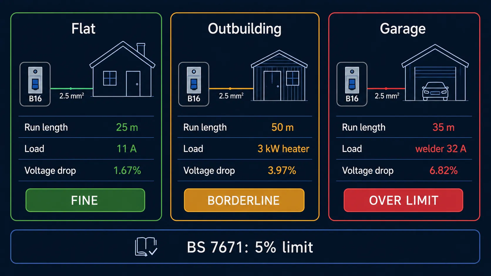
Theory's theory. Now three typical jobs that'll turn up with your own house. Take the formula, drop your numbers in, read the verdict. These three cover most real situations: a short run in a flat, all good; a medium run to an outbuilding, on the edge; a long run under a heavy load, a disaster. Grab a calculator and work them through with me.
Flat — 25 m to the washing machine, 2.5 mm², 11 A
Given: I = 11 A (a 2.4 kW machine), L = 25 m, S = 2.5 mm² copper, U = 230 V.
The sum:
ΔU = 2 × 11 × 25 × 0.0175 / 2.5
   = (22 × 25 × 0.0175) / 2.5
   = (550 × 0.0175) / 2.5
   = 9.625 / 2.5
   = 3.85 V
As a percentage: 3.85 / 230 × 100 = 1.67%
Verdict: fine. The machine still sees 226 V at the terminals — it'll never notice. This is the everyday case in a flat. I've wired plenty of boards with the usual 2.5 mm² over 25–30 m and never once had to swap a cable over losses. If your flat's within 30 metres of the board and the sockets are on 2.5 mm², sleep easy — you've a comfortable margin under the limit.
Garden office / outbuilding — 50 m, a 3 kW heater, 2.5 mm²
What we've got: P = 3000 W, so I = 3000 / 230 = 13.04 A, L = 50 m, S = 2.5 mm² copper.
Working it:
ΔU = 2 × 13.04 × 50 × 0.0175 / 2.5
   = (26.08 × 50 × 0.0175) / 2.5
   = (1304 × 0.0175) / 2.5
   = 22.82 / 2.5
   = 9.13 V
As a percentage of 230 V: 9.13 / 230 × 100 = 3.97%
Verdict: borderline. It passes on paper (3.97 < 5%), but there's no headroom left. The heater's start-up adds another 20% on top, and you're over the red line. This is the outbuilding from the top of the article: 30–50 m of 2.5 mm² plus a pump running at the same time, and the drop sails past 5%. The heater starts cutting out and runs cold for a week before anyone twigs.
Recommendation: go to 4 mm². Recalculate: 2 × 13.6 × 50 × 0.0175 / 4 = 5.95 V = 2.6%. Twice the margin. The extra for the fatter cable over 50 m is roughly £30–£60 (a few pounds a metre, varies by supplier) — cheaper than re-doing it once it's all buried in the wall. A long underground run to an outbuilding usually wants SWA (steel-wired armoured) anyway, sized the same way.
Long runs (40 m and up) to an outbuilding or garage, feeding a heavy load — a heater, a pump, a shower — always work out the drop. In a flat it's nearly always fine; on a long external run it's often borderline.
Garage — 35 m, an inverter welder, 32 A peak, 2.5 mm²
Inputs: I = 32 A (peak while striking the arc), L = 35 m, S = 2.5 mm² copper.
Plug in:
ΔU = 2 × 32 × 35 × 0.0175 / 2.5
   = (64 × 35 × 0.0175) / 2.5
   = (2240 × 0.0175) / 2.5
   = 39.2 / 2.5
   = 15.68 V
As a percentage: 15.68 / 230 × 100 = 6.82%
Verdict: over the limit. Striking the arc is effectively a short-circuit of the electrode against the metal, so the drop spikes instantly to 25–30 V. The arc starts to wander, the weld comes out crooked, full of pinholes. A mate welded in his garage for six months moaning that "the arc keeps jumping, must be a duff machine." I had a look — same old 2.5 mm² over 35 metres. There was your "duff machine" — it was in the cable.
Recommendation: 6 mm² copper. Recalculate: 2 × 32 × 35 × 0.0175 / 6 = 6.53 V = 2.84%. Back inside the limit, with margin for the start-up spikes. The cable's pricier (6 mm² T&E is roughly double the per-metre cost of 2.5), but it's a one-off, and the welder stops spitting.
Cheat-sheet: maximum run length at 5% drop (copper, 230 V)
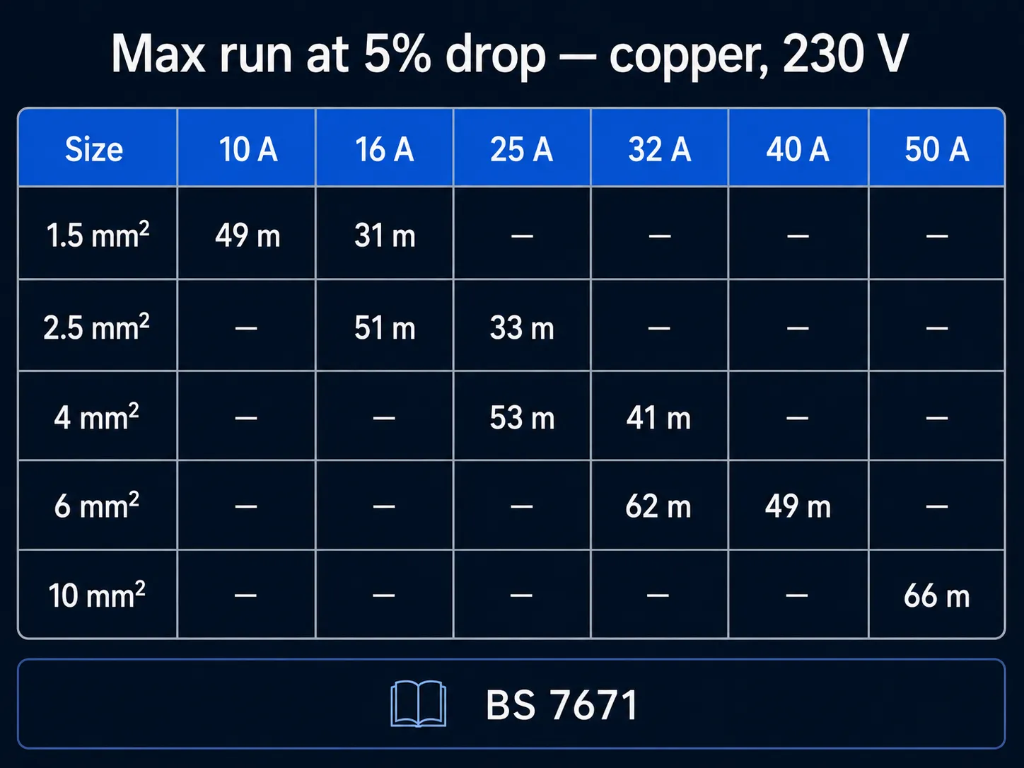
Here's a ready-made cheat-sheet. I print one out and keep it by the board:
| Size | I = 10 A | I = 16 A | I = 25 A | I = 32 A | I = 40 A | I = 50 A |
|---|---|---|---|---|---|---|
| 1.5 mm² | 49 m | 31 m | — | — | — | — |
| 2.5 mm² | — | 51 m | 33 m | — | — | — |
| 4 mm² | — | — | 53 m | 41 m | — | — |
| 6 mm² | — | — | — | 62 m | 49 m | — |
| 10 mm² | — | — | — | — | — | 66 m |
The dashes mean the cable can't carry that current on its current rating (its ampacity) regardless of the drop. The rule: pick the size for the current first with the cable cross-section calculator, then check the drop for your length. If your combination isn't in the table, either the cable's too small for the current or the length's beyond the limit — recalculate with a thicker size.
The formula that builds the table: L_max = ΔU × S / (2 × I × ρ), where ΔU = 11.5 V (5% of 230 V) and ρ = 0.0175 for copper.
How to cut the drop — three levers
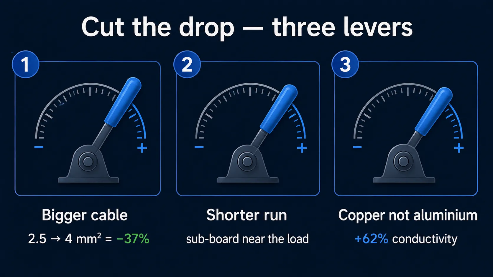
Worked it out and it came over 5%? There are three ways to fix it. They work together — you can yank one lever hard, or two of them a bit. The cheapest and most effective is the first; the others are extras.
Increase the cable size
The obvious one. ΔU is inversely proportional to S, so:
- 2.5 → 4 mm²: drop −37%
- 2.5 → 6 mm²: drop −58%
- 4 → 6 mm²: drop −33%
The extra for the fatter size is a few pounds a metre. On a 30 m run that's tens of pounds, one-off. Re-doing it later — chasing out the wall, ripping the cable out, re-running, re-plastering, re-painting — costs five to ten times as much. So my standing advice: when you're torn between two sizes, take the thicker. It's nearly always cheaper than the redo.
Shorten the run — a separate circuit or a sub-board
Rather than dragging a cable from the main consumer unit across the whole house, drop a small sub-board (a garage CU or a switch-fuse) closer to the load. Or move the immersion nearer the supply. Sometimes shifting the board five metres beats running 4 mm² instead of 2.5.
A friend planned 50 m to an outbuilding heater. We worked it out — he needed 6 mm². I suggested a small sub-board on the outbuilding wall instead, fed by a 4 mm² sub-main, leaving only 8 m to the heater itself. It came out cheaper overall, with less chasing. You can lay the whole thing out in the ElectroBoard configurator — it'll cost the parts for you too.
Switch to copper (if it's aluminium)
Aluminium has 1.6 times the resistivity of copper (62% of the conductivity). Aluminium 4 mm² is, by resistance, roughly copper 2.5 mm². So an old run in 2.5 mm² aluminium behaves, for voltage drop, like copper 1.5 mm² — which is why an old board with aluminium sub-mains drops out when you run two heavy things at once.
Going from aluminium to copper cuts the drop by about 37% for the same size. If there's 2.5 mm² aluminium in the wall, replacing it with 2.5 mm² copper is like stepping up to 4 mm². Copper also doesn't crack when you bend it and doesn't creep under the terminal screw — the old aluminium curse, where a year on the joint oxidises, loosens and starts to arc.
Where this fits with the rest of the board
Voltage drop is only one piece of the puzzle. There's the breaker, the RCD, the cable size, the earthing — they all work as one system. Where to look next:
- The breaker can't see the drop — there's a separate guide to choosing an MCB with the cable-to-breaker table and why Type B, C and D curves matter on a British supply.
- How it all comes together in a flat's board — the walkthrough on assembling a consumer unit for a one-bed flat has a ready board layout, a parts list and a costing.
Voltage drop is the parameter the breaker won't catch, the meter won't show, and the appliance feels first. Check your run in the calculator or work it out with the formula from this article — three minutes of your time can save a shower, an immersion or a welder.
Plan your board in the free ElectroBoard configurator. Drop in MCBs, RCBOs and cables, and get a finished layout, a parts list and a costing. Work the voltage drop out per circuit with the calculator.
FAQ
In short
Four things. I run them in my head every time I plan a long circuit.
First. The breaker is blind to voltage drop. It counts amps, not volts. "The breaker holds" does not mean "the voltage is fine." Different parameters, different protections, parallel universes.
Second. The formula is simple: ΔU = 2 × I × L × ρ / S for single-phase, and for three-phase you swap the 2 for √3 (1.732). Resistivity: copper 0.0175, aluminium 0.028 Ω·mm²/m. Out on the job, use the mV/A/m figure from BS 7671 Appendix 4 instead — same answer, pre-chewed. Ceilings: 5% (11.5 V at 230 V) for power, 3% (6.9 V) for lighting.
Third. When you've gone over the limit, there are three levers: a thicker conductor (the cheapest fix), a shorter run (sometimes move the board or fit a sub-board), copper instead of aluminium (if it's old wiring). They work together, so combine them.
And fourth. Don't guess, work it out. A few minutes in the calculator or with a pencil saves you a small fortune on a new shower or immersion, and a long argument with a service engineer. Learned the hard way, more than once.